Circuit Diagram Of A Logic Probe Using Protias 8 Electrical
What is a logic probe? Logic probe Logic probe circuit project high low transition pulse learningelectronics
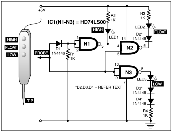
Logic Tester Circuit Diagram
How to use proteus 8 professional 555 logic probe 555 logic probe circuit schematic diagram Probe logic lm339 circuit quad comparator diyodemag
Probe logic circuit simple electronic projects
Logic tester circuit diagramLogic probe circuit diagram Probe logic circuit simple ideas eleccircuit circuitsLogic probe.
Circuit diagram of logic probeHow to convert circuit diagrams pcb layout in proteus How to build a logic probe6 simple logic probe circuits ideas.

Logic 555 probe schematic tester
Electrical – proteus 8 simulation errors. loaded netlist – valuableDesign and make: the ubiquitous logic probe Logic probeLogic circuit probe ttl state projects electronics circuits simple three diagram ic gates project nand hitachi using electronic quad full.
Logic pulser6 simple logic probe circuits ideas Digital logic probe for troubleshooting ttl and cmos circuitsCircuit diagram logic probe.

Logic probe circuit cmos diagram digital
Diy logic probe: step by step guideProbe logic circuit simple 2010 popular tag rend august gr next 4 useful logic probe circuits explored – homemade circuit projectsLogic probe circuit digital diagram seekic circuits.
Diy tools—build your own logic probeCmos logic probe circuit diagram 6 simple logic probe circuits ideas8: probe circuit schematic..

Logic probe schematic diy build own tools larger click allaboutcircuits
Logic probe digital breadboard circuit lab ttl cmos setup troubleshooting circuits embeddedDigital logic probe for troubleshooting ttl and cmos circuits Ttl three-state logic probe circuit diagram projectLogic probe circuit diagram.
Logic_probeProbe logic circuit indicator frequency range gadgetronicx How to use voltage and current probe in proteus 8 software.Design project: logic probe : worksheet.

Circuit probe logic transistor mini eleccircuit
Simple logic probeLogic probe – electronic circuit diagram Full circuit diagram for the design results and discussion proteus 8.10Probe logic.
Electronic projectsLogic probe with frequency range indicator Circuit logic probe indicator circuits level simple tester homemade build diagram ledLogic probe circuit simple ic ideas eleccircuit gate not circuits.
Circuit logic diagram probe led
Logic probe with pulseSolution: logic probe circuit diagram .
.


